
Project
The purpose of this work is to provide a method to extract Geographic Coordinates of detected targets located on a hilly terrain, from a flying drone. The full project has been carried out by Big & Deep Co., Ltd., Seoul, South-Korea.
A quadcopter drone with a stabilized mounted camera is used for the terrain scanning. The payload holding the camera provides relative angles from the frame body, in yaw, pitch and roll. The drone holds a GPS which provides its geodetic position, and an accelerometer for altitude and attitude.
A digital terrain has been used for the proof of concept, just to provide realistic images from the camera. Some targets are set on the scene for each mission.
An image processing model, using AI for recognition, will detect targets on images provided by the drone during the mission. Once a target is suspected, the position on the image is sent back to the drone. At this moment, the coordinates resoluteness will initiate.
The quadcopter
For this project, the drone dynamic is not an essential component as, in fine, the camera is stabilized. But to make it more realistic, we are using a mathematical model based on automatic controllers.
Dynamic
The body motion is handled using P, PI and PID controllers. Such controllers are used for accelerations along x/y axis, altitude gain, pitch and roll command and stability. Motor thrusts are used for altitude and acceleration. A perturbation factor propagates body vibrations.
The obtained result is satisfactory. The quadcopter is stable enough and reacts well to applied forces.
Position control
The position controller overrides the cinematic component and uses a PID controller to drive the body at a given 3D position. Some parameters ensure there is no amplification nor resonance and that the drone will smoothly join the position and not oscillate and distort around it.
The drone is equipped with a GPS and gyro to keep the accuracy of it’s position and altitude on the terrain. This position is converted in latitude and longitude. Errors can be added either as constant or as a linear drift over time.
For testing, we position a goto-point at a certain distance of the drone and make it rejoin it (see video below). If the point is moved (with a joystick), the drone will constantly adjust its course.
Trajectory
To make the drone follow a trajectory, we use a specific module which moves the goto-point along the trajectory, at a specific speed. The trajectory speed cannot be greater than the drone maximum speed. Also, the module always waits for the drone to be close enough to start moving itself.
Payload Camera
The drone is carrying a camera mounted on a rotating and stabilized payload. The attitude and orientation is controlled by the software. Vibrations can be added, although there are of few use as the processing is done on fix images and not on the video stream. Errors in angles (azimuth, pitch and roll) of the payload versus the frame body can be added (fix, random or drift).
Terrain
For the purpose of the project, a simple and old OpenSceneGraph database (courtesy of TrianGraphics) is used. vsTASKER can build a map out of this format and display it in 3D. This will be convenient for mission preparation and real time monitoring. The position of the target on the map can be checked in 3D as line of sight is an important part of the detection process.
The digital elevation twin of the terrain is not provided to the drone and will be used on the second part of this project. The first approach is to solve the absence of the terrain profile.
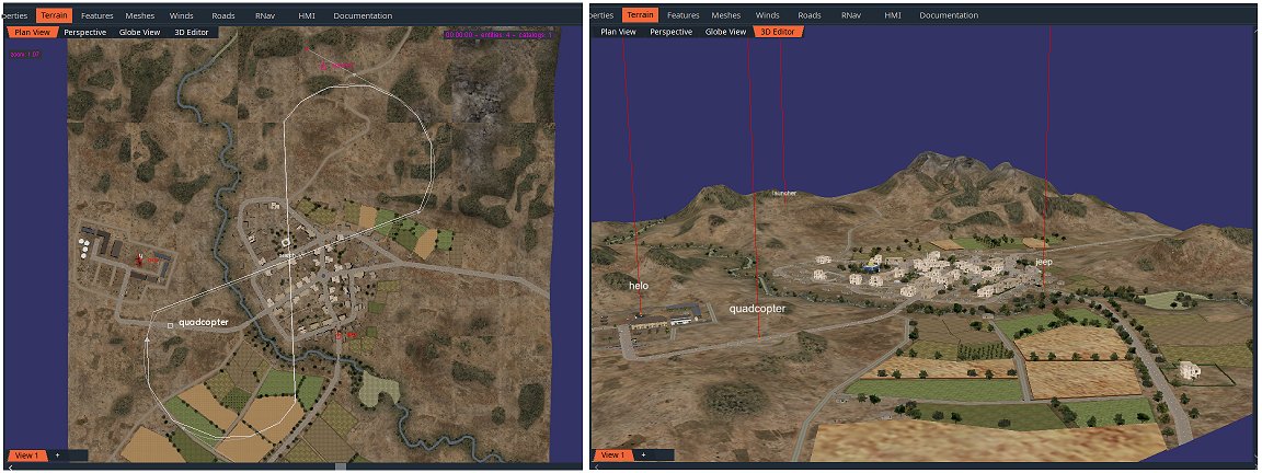
Targets
Three targets has been positioned on the terrain. They are stationery ground vehicles: one helicopter, one Humvee and one missile launcher.
Each of these targets have a visual signature which allows the Image Analyzer (based on machine learning) to recognize them. It may take some time according to the angle of view and the distance. Enough pixels should be provided to trigger the point of interest (Poi).
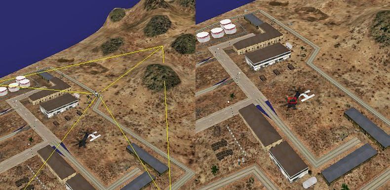
When something is detected, the drone receives the (x,y) coordinates of the Poi on the image. Knowing the Field of View (Fov) and the payload orientation at the time of the image (the detection may come with a delay since the image analyzer has it’s own processing time), the drone is capable of zooming toward the estimated Poi. With a higher resolution image, the analyzer can confirm or invalid the Poi as a target.
If the Poi is recognized as a valid target, the drone will suspend the trajectory and start a specific pattern to determine the target geodetic position. During this process, the drone is continuously using the feedback of the Image Analyzer to center the camera focus on the Poi (red square on image).
Workflow
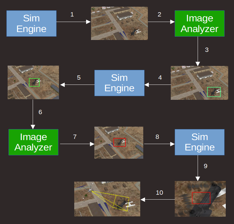
- The Simulation Engine (SE) rotates the drone payload to scan the area around it, at high Fov. Every second, a snapshot is taken and sent to the Image Analyzer.
- The Image Analyzer (IA) processes the received snapshot to identify a potential threat.
- When a point of interest (Poi) is found on the image, the IA mark it with a green square.
- The coordinates on the image of the square center is sent to the SE.
- The SE stops scanning the area and moves the payload to center the Poi coordinates.
- Snapshots are sent to the IA continuously to correct the centering from the updated Poi coordinates.
- If the IA identifies a potential threat, the mark becomes red.
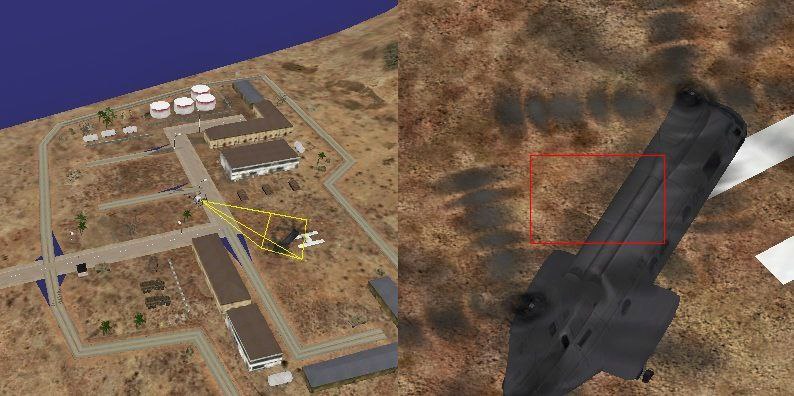
- The SE stops the drone motion and starts the triangulation maneuver.
- Camera zooms on the Poi to allow more accurate recognition. Snapshots are continuously sent to the IA to maintain the centering of the target using the mark position acknowledge.
- The payload angles and drone coordinates will be used to estimate the target geodetic location.
Logics
The drone is equipped with several logics which are activated according to the different phases of the flight.
The two most important ones are: search and acquire:

The Search logic is rotating the payload (azimuth) and controls its elevation at each full revolution (360°), from -20° to -40°, by step of 10°. A snapshot is taken every second and sent to the Image Analyzer. The logic is left as soon as a Poi is notified.
The Acquire logic is controlling the copter motion for each Poi detection. Snapshot actions are performing ray shooting as explained below. The difference between a task (green rectangle) and an action (ellipse) objects is that a task is an iterative process which takes time (such as a C++ procedure) and quits when the job is done, while an action is a one cycle job (like a function), which quits immediately.
Triangulation
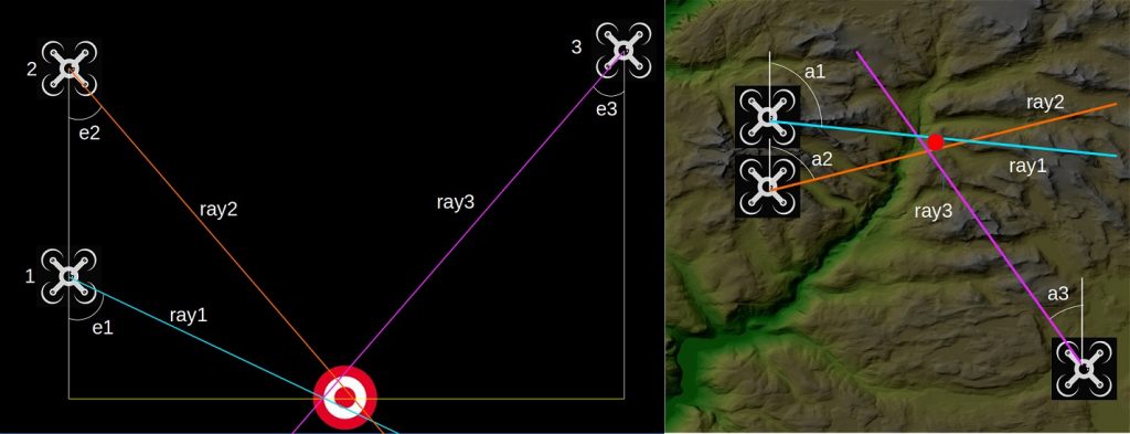
Since the only known values are the drone geodetic position and the absolute angle values of the payload in terms of azimuth (0° = north) and elevation (0° = down), it is necessary to make several measures before extracting the target position.
The logic Acquire is handling these measurements:
- Shot a ray 1 from the drone center of gravity with azimuth and elevation of the camera payload;
- Flies up by 300 meters while maintaining the Poi (target) centered;
- Shot a ray 2;
- Slide another 300 meters on random direction and shot ray 3;
- Find on each ray the closest point from the two others (sliding rings algorithm);
- Compute the centroid of the 3 points as the Poi coordinates.
Sliding Rings Algorithm
This algorithm gives the two closest points on two non-intersecting 3D segments. The principle is to slide two rings along each segment until the distance is minimal. The process is iterative and stops when the step falls below a certain small value. The step starts at 1/3 of the smallest segment then is divided by 2 at each iteration. An iteration works around the ring position found at the previous iteration until the step is small enough to give up.
1- put ring rA on one extremity of segment A
2- put ring rB on one extremity of segment B
3- compute the distance d0 between the two rings at position pA0 and pB0
4- slide rA and rB using the step, then compute the distance d1 between pA1 and pB1
5- if d1 is smaller or equal to d0, goto 3
6- if d1 is greater, must determine which ring goes away:
– if distance from pA0 to pB1 is smaller than pA1 to pB1, then rA should reverse way
– if distance from pB0 to pA1 is smaller than pB1 to pA1, then rB should reverse way
– divide step by 2
– if step less than 0.5m, return pA1 and pB1
– else goto 3
7- if rA and rB reached the other extremity of the segment, cannot find one.
Result on Video
The following video show the drone flying along a predefined trajectory and detecting 3 targets. The 3D terrain for the scenery is rendered using OpenSceneGraph and the database is an old courtesy of TrianGraphics.
Future Work
This prototype is the first stage of a more complete project. Better Image Analyzer is on work. More realistic scenery will be used based on IG like Unreal. A more accurate copter dynamic model could be used although it is not that important as long as the payload is stabilized and images are not too fuzzy.
The following topics will be covered on due time and the document updated accordingly.
Statistics
Once a scenario is defined, vsTASKER can use its batch capability to chain thousands of run at high speed (the maximum the Image Analyzer can support), while changing some parameters at each run (like scanning Fov, copter speed, payload rotation speed, scanning pattern, vibrations, quality of the camera, etc.) and record the probability and time of detection, for later analysis.
Moving targets
The previous triangulation computations are based on stationary targets. When the Poi is moving, the time between the ray shots is reducing greatly the accuracy of the localization. This can be reduced by only throwing 2 rays for a quick approximation, then making the copter stationary and then refine the position according to payload adjustment angles to keep the target centered. The first problem to fix is to determine if the Poi is stationary or moving. This could only be provided by the Image Analyzer.
Using DEM terrain
If the terrain elevation is already known and loaded into the copter, the Poi localization shall become straightforward as only one ray shot would be sufficient to determine the ground coordinates (intersection of the ray with the terrain surface).
With such digital terrain onboard, coordinates could be computed on the fly, at real-time, for any part of the image without making the copter change it’s course. Multiple Poi could then be localized at the same time.
Conversely, the copter could also focus and zoom on any provided Lat Lon coordinates, as the altitude would be extracted from the digital terrain, the vector could be computed and payload would be orientated accordingly to obtained angles.