What we want to do
In this presentation, we will learn how to setup vsTASKER to build from scratch a pushback, tow and (multi-carriage) trailer simulator.
We’ll start with an empty database and end up with a visual demonstrator using OpenSceneGraph and some free models available on Internet. vsTASKER used is v6.2. This way will give you an idea of the openness of the product and its possibilities as we will not used any canned devices or predefined components.
Preparation
In vsTASKER, most of the entities are represented by a 3 dimensional coordinates located at their centre of gravity, a velocity vector plus some attitude values (heading, pitch and roll). These variables are modified by equations of motion (entity dynamics) during runtime. Because we will run the new component at high frequency, we won’t have to compute the trajectories with tons of equations but just let the vectors push and pull joints altogether. The result would normally conserve physic laws or stay close enough for the purpose of our simulation. We will see later that this assumption is correct.
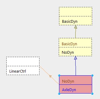
For this exercise, we will need to create a new dynamic motion component for the chassis with simple equations based on Newton laws and vector forces. We will call this component AxleDyn as it will handle axles and tires. It will inherit from NoDyn component as we do not want to redefine all the pure virtual functions of BasicDyn class
Building the dynamic component
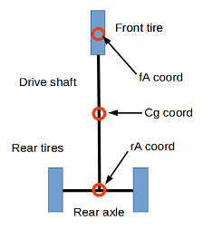
The AxleDyn component will have two axles separated by a drive shaft. We will only need to bother about the centre of each of these elements as they will be located under the carriage frame. At first, we will only set 3 tires. The front one connected to the steering wheel and the two rear tires, fixed on the rear axle, like the picture aside. Our chassis replica will only move the 3 points fA, rA and cG. fA and rA are connected by a l length shaft (see below) and the two rear tires are distanced by w meters (width of the chassis). The axles are always perpendicular to the shaft and this one gives the azimuth of the chassis.
We will need now to define the interface of our component. The more parameters we can let the user define, the more adaptable will it be when time to use the 3D will come. As vsTASKER automatically generates the user interface when data is preceded with //&&, we will do it for most of the variables.
This interface (above) will generate a configuration interface for the user to change the default values:
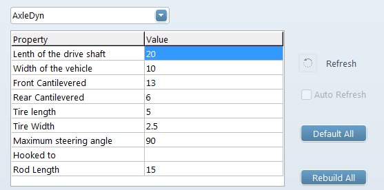
Now, time to set the component variables used by the model.
We can see that steer (the steering wheel) is based on a control loop component (LinearCtrl) used to soften the value changes and provide a kind of inertia (the current value will slightly change towards the target one over time).
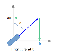
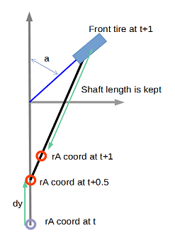
Now, we will write the mathematical formulas for the model. For that, we need to remain simple by projecting vectors on each axis. Every cycle, the front axle will move according to the speed vector. At t0, according to the steering angle of the front tire (a) 2 projected distances are computed. One along the drive shaft axis (dy) and the second one on its perpendicular (dx). At t1, the front axle will move along the vector.
The rear axle will move in two steps. First move of (dx) along the shaft at t0 and the second move along the shaft at t1, to keep the final length equal to (l). In reality, what happens is a combination of the two.
Testing on OpenGL
Once the mathematics has been translated into code, we need to check the result on a 2D display. vsTASKER provides this capability out of the box. We just need to attach an OpenGL viewer and write the OpenGL code to display the frame and the tires shapes on the output window.
To make the testing more interesting, we can add some colored ground traces with simple lines added at the end of the runtime code:
And to display it, just add the following code to the function drawOn():
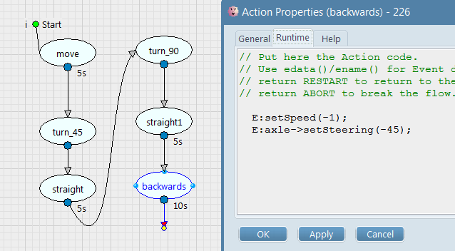
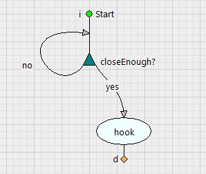
In order to maneuver the vehicle, we define a logic made of successive Actions which controls the speed and the steering wheel or the tractor (direct call of the AxleDyn API functions):
Giving the following result (click on the video below):
Confronting the data
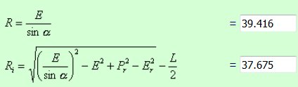
To insure that our dynamic is physically correct, we need to measure the turn radius of each tire for a given steering angle, and compare the data with the theoretical values. For that, we will store the position of each tire during a full circle (to get the circumference) then deduct the radius by dividing by 2*PI.
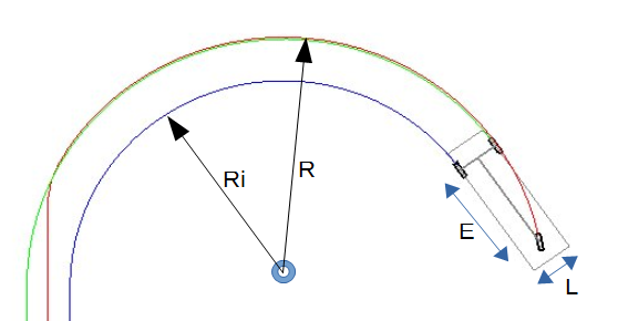
With L: 2.5 m, E: 6.2 m, steering angle: 10°, our simulation gives: R: 39.4, Ri: 37.6
When confronted with theoretical data, we can see we are very good indeed:
Adding trailers
Now, it is time to test adding a trailer on the rear hook of our vehicle.
For that, we need to extend the AxleDyn component with the name of the tractor (entity) to hook the trailer to. Then, we will add a trailer (entity) into the scenario, attach an AxleDyn component to it, setup parameters to hook to the current tractor and let the chassis (component) be automatically driver by the tractor (hook).
For that, let extend the component the following way:
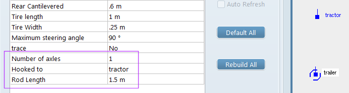
Now, time to add two trailers, attached together up to the tractor vehicle (see image below). We can also notice that we have specified each trailer has only one axle (the rear one) and a tow bar of 1.5 meter long.
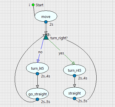
Now, we define a fairly simple logic to make the tractor wander randomly in the area:
and we obtain the following result (click on the video below):
Checking with a 2 axles trailer
Now, let’s see how the dynamic model works with a two axles trailer. We decide that the tow bar is no more directing the front wheel but let this one automatically adjust itself according to the towing direction. Here is the result, proving that decomposition of complex interactions using simple concepts produces a realistic outcome (tow bar of 4 meters) :
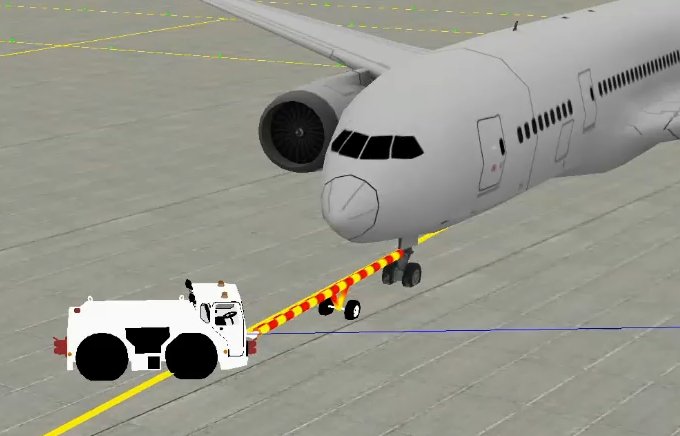
Pushback using a tow bar
At this time, we are close enough to reach the purpose of this exercise: pushback (of an aircraft) using a tug. In real life, there is two kind of pushback methods: using a tow-bar and without.
Because pushing is much sensitive than pulling, we will use a gamepad to control the speed and the steering of the tug. Adding such a component is straightforward as the basic controller is already available in the vsTASKER built-in component library. Writing the interface class between the controller and the tug will be easy.
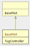
First thing is to inherit from the base component which reads the gamepad values and connect them to the AxleDyn API.
Now, if we want to improve the simulation by making sure the front wheel of the aircraft stays in the angle limits, let’s check them and update the display to turn the color to red when tow bar is broken.
Giving the following result (click on the video below):
Setting OSG airport and 3D models
We are getting closer to the final result. We need now to use OSG to make the trainer more realistic. This part is the most challenging as combining 2D OpenGL algorithms with 3D physical models is always touchy. Happily, vsTASKER provides some nice tools and environment to ease this process.
First, we download a demo terrain database (courtesy of TrianGraphics) and we dropped on it some 3D models downloaded from TurboSquid website. The video below explains the process:
We now need to adjust the chassis frame of our AxleDyn model to the dimensions and tire locations of both aircraft and tug vehicles. For that, it is enough to create some components tailored to display on the OSG output visual cues (location of the AxleDyn tires, vertical lines, etc) like we did previously on the test OpenGL window. Each component will be attached to their corresponding entity:
We are now able to perfectly match the dimensions of our AxleDyn model with the real dimensions of the 3D object it carries (aircraft, tow bar and tug) which are sometimes unknown or because the centre of reference of some 3D models are not always set in the middle.
Once the camera is in place, changing the settings in vsTASKER, using the generated parameter panels allows visual adjustment, like shown in the following video:
Finally, remains the tug automatic hooking of the tow bar to start the pushing. For that, we write a logic which computes the distance between the tug front hook and the tow bar hook in order to attach them as soon as below a given distance. It will be up to the trainee to drive (using the gamepad) the tug vehicle towards the aircraft tow bar.
Final results
In the following two videos, you will see the final result of this exercise. First one is the pushback (with one try breaking the tow bar).
The second video is pulling the aircraft (much easier process). To perform that, we just changed the tug hook setting from Front to Rear in the parameters window and we let the magic.
Couple of days of work for one guy with a normal knowledge of vsTASKER (including OSG and writing this document) were necessary to carry out this prototype. If you are convinced, try our software yourself and see how it can help you with your ongoing or future projects.