Yann Takvorian
VirtualSim
Nice, France
yann@virtualsim.com
Submitted at Interservice/Industry Training, Simulation
and Education Conference (I/ITSEC) 2014
ABSTRACT
Unmanned Aerial Vehicles (UAVs) represent ideal platforms for automated decision making. The use of modeling and simulation for building and testing autonomous behaviors can drastically enforce the capabilities of unmanned aircraft, skills of ground operators and usefulness of missions.
The actual unmanned aircraft developed for the civilian market (e.g., photography, search, surveillance) have the drawback of being primarily remote-controlled. To reduce the difficulty of manual piloting, it becomes advantageous to run software to simulate the environment for testing the mission prior to actual operation. Such software can automatically compute the best path to cover an area (i.e., path or trajectory planning) according to sensor capabilities, image resolution, battery autonomy, maximum altitude and atmospheric conditions, to control the aircraft automatically, without the need of a human visually controlling.
In this paper, the use of a synthetic environment to test a mission, using the popular MAVLink communication protocol, will be presented with recommendations regarding the setup of a simple trajectory to perform a real autonomous flight.
ABOUT THE AUTHORS
Yann Takvorian graduated from Computer Science Engineering in 1991. He studied Artificial Intelligence in Paris then got his first job at Airbus Training to develop computer based trainers for pilots. Since then, he spent his career worldwide in the simulation business as a presales engineer and consultant.
In 2004, he founded and still run VirtualSim, that develops and sells worldwide a scenario editor COTS product for runtime simulation systems.
BACKGROUND
Historically, unmanned aircraft (e.g., micro-air vehicles [MAV]s), like robots, belonged to science fiction. Later, they were used by military as quick, efficient, furtive and safe unmanned forward observers (New bird shaped UAS, 2013). Eventually, autonomous capability was added by embedding flight plan and intelligence, global positioning systems (GPS) and image recognition (Munoz, 2014). Unmanned aircraft can cooperate, loiter, wait for instruction, fly in formation, drop ammunition, help in indirect fire in effective live-saving warfare missions (Institute for Near East and Gulf Military Analysis, 2011).
Conversely, hobbyists are still using radio-control for operation of their model airplanes under 400 ft and within visual line of sight, limiting themselves to acrobatic figures and, ultimately, not losing sight of their toy. However, with the technology evolution, miniaturization, and price drop for gyroscopes and tachometers, remote controlled aircraft have become increasingly more reliable and popular. Some flying wings can do automatic acrobatic figures and landing or return-home on signal loss, approaching the complexity and capabilities of unmanned aircraft systems (UAS).
With the miniaturization of electric engines, first easy-to-fly rotorcrafts are now sold in popular shops. The main advantage is that on-board camera can be used as a remote eye, providing the pilot a virtual flying experience (e.g., first-person-perspective [FPV]). Compared to fixed-wings, a multicopter is easier to control in all directions and can hover or hold above a target. Complex algorithms have already produced some outstanding and acclaimed live demonstrations (D’Andrea, 2013).
Today, some manufacturers are selling multicopters equipped with on-board cameras, sensors and controllable using WiFi, from a smart-phone or laptop or dedicated long-range radio emitters. Some of the more complex systems use GPS receivers and are compatible with the MAVlink protocol (QGroundControl, n.d.) to receive a flight-plan for autonomous operations. The gap between a fly-by-hand toy and a UAS is dramatically reduced through incorporation of embedded electronics: “These personal drones can do everything that military drones can, aside from blow up stuff” (Anderson, 2012, para. 3).
PREPARATION
The purpose of this study is to prepare and realize autonomous flights for a quad copter commonly available on internet and popular stores, at a price below $500. The product A.R. Drone from Parrot SA (2012) was selected for this research project.
The project was realized in several phases, from the inside office, using a simulation toolkit up to the outside field, with the real machine, in order to tune the components and prove the usefulness of the concept. The finding of 10 minutes operation per battery on such a platform forbids trial and error in mission planning. Upstream simulation tests were envisioned to lead to a successful real flight, either on a long mission or several short one, within the battery life.
This project also features the design of a virtual control-panel prototype that works in several modes: “full simulation”, “real world” and “hybrid combination”, mainly for monitoring and tuning.
Scenario Edition
The idea was to simulate the drone flight over a given area prior to real flight. A map downloader terrain (e.g., Global Mapper) was used to import the terrain map and the elevation data. For the mission preparation, vsTASKER simulation SDK (VirtualSim, n.d.) was selected to display the maps, handle the components, logic and to build the control panel.
The outdoor area is far away from habitations, clear of obstacles, wire and trees (figure 1). The first purpose is to compare the simulated camera video output with the real recording.
The Parrot drone flight dynamic was replicated according to its characteristics. Linear models are sufficient to approach anticipated performances. Therefore, high fidelity representation at this stage was not necessary. Accelerations (e.g., vertical and horizontal), maximum speeds and tilt angles were sufficient to start the project. Models are adjustable later (i.e., during tuning phase), by replacing linear functions with real data curves.
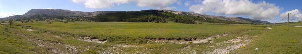
Fig. 1: Field playing zone
Figure 2 shows a simple trajectory defined by waypoints in space. The take-off and landing points are both located on the parking lot, aside of the road. The map tiles are correctly geo-referenced. Coordinates (i.e., Latitude and Longitude) of the raster images have been correlated on site will a cellphone GPS.
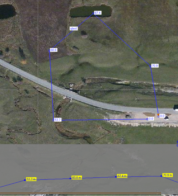
Fig. 2: Scenario definition
Figure 3 emphasizes the coverage of the simulated camera on the ground, according to the altitude above terrain and based on the technical aperture specifications of the on-board equipment. The simulated camera component controls the camera over the loaded terrain and produces a video stream which is then recorded on disk. The quality is low, as portions of the raster map are magnified, but the result gives a good approximation of what will be depicted in the real movie.
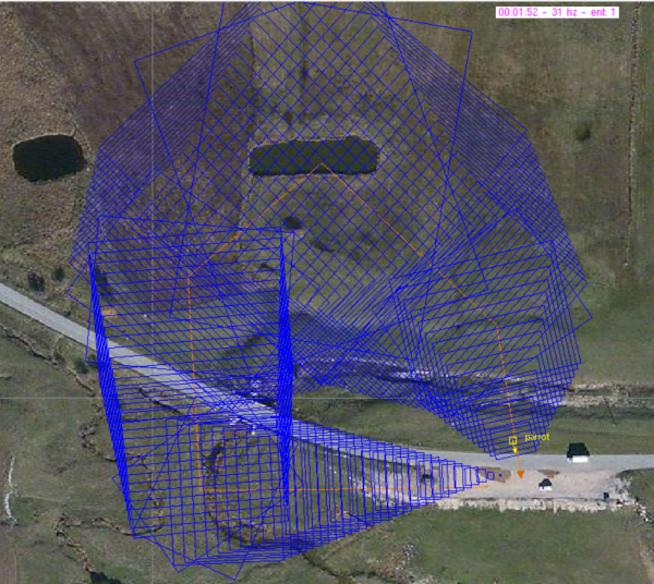
Fig. 3: Predicted camera coverage on ground
Ground Control Panel
On the field, a Ground Control Panel (GCP) is run on a dedicated laptop. The simulation toolkit provides an OpenGL based HMI builder to fulfill this requirement. The GCP is used in three modes:
1- Simulated mode during mission preparation;
2- Real mode, connected to the drone, on the field;
3- Hybrid mode, to cross-check real flight data against simulated ones. The system automatically adjusts gains of simulated components (e.g., flight dynamic, battery) using information sent back from the quad copter.
The GCP also displays the map with the Parrot symbol position, user-defined trajectories and control buttons.
OpenSceneGraph was selected for the simulated output. An OSG camera is mounted on the simulated quad copter and setup in such way to replicate the field of view of the real mounted fix camera. The visual feedback produced during the course of the simulation was sufficient to obtain a first approximation of the real observation.
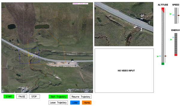
Fig. 4: HMI Control Panel generated by vsTASKER to simulate the quad copter flight
Logic
Basic behavior of the UAS was defined using the logic diagram feature (i.e., state-chart) of the simulation tool. Having behaviors described graphically was essential to the GCP completion. Changes in sequences were numerous and debugging was simple as all diagrams illuminate during runtime according to their own status.
Figure 5 synthesizes how GCP buttons are processed. For i.e., the start button (figure 4) raises a “START” event that forces the quad copter to either hover at 2 meters then memorizes coordinates (if simulation is not paused) or resumes the trajectory (if simulation is paused and home mode not engaged).
“Home” or “Stop” buttons (figure 4) force the quad copter to quit the trajectory (if any) then engage the home mode, making the copter to return to the initially memorized position, then land on the ground.
To achieve the goal of this project, every object in the diagram holds their own specific C++ code. The programming of this project implied dozen of more complex state-charts than the part we extracted (and simplified) in figure 5 for clarity purpose.
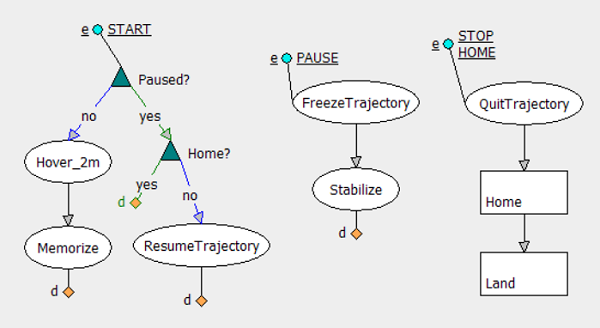
Fig. 5: Simulated drone extracted logic
The battery simulation requested a dedicated task (“Battery”, figure 6) that constantly checks the distance of the quad copter from the memorized initial position. Homing mode is automatically engaged when a minimum threshold if reached, to prevent losing the aircraft on the field. Because several endurance tests have been carried out in various situations, the battery model is accurate enough to trust its assessments, mostly in windy conditions.
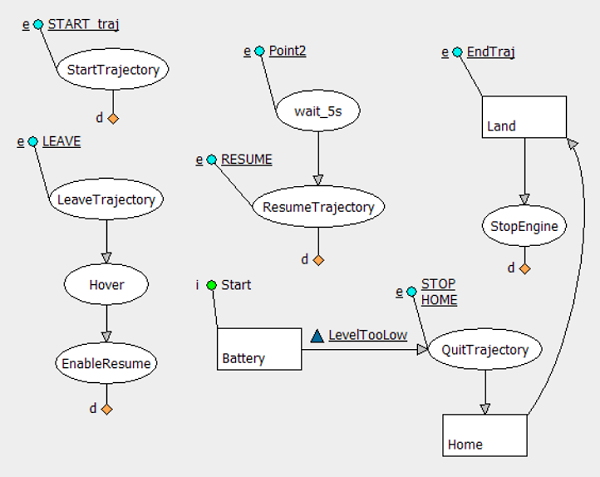
Fig. 6: Trajectory logic and Homing
Components
The real-time simulation engine (i.e., RTC) embeds the behaviors, components, MAVLink support and scenario definitions. It occupies one thread of the application and cycles at 30hz. The GCP (i.e., OpenGL user console) is run on another thread. All different parts of the RTC working together, as shown in figure 7.
OSG: OpenSceneGraph camera outputs on the GDI window what the virtual camera sees of the terrain map. The camera receives position and attitude from the dynamic component and do the sight computations.
Dynamic: Flight dynamic is based on linear equations. It mimics the quad copter performances. The component receives data from the logic and outputs computed values to GCP. This component is also taking into account the wind information provided by some tubes on the map. Wind does not impact much on trajectory as the copter automatically compensates the drift, but it does change the ground speed and therefore the battery consumption in situation of head or tailwind.
Logic: The state-charts get data from the mission plan and/or GCP manual requests (e.g., button, sliders, knobs). It controls the dynamic component and displays some symbols on the map.
Map: Displays on GCP the raster map, elevation data, quad copter icon and the flight-plans.
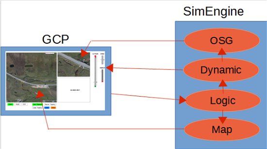
Fig. 7: Mission Planner System
HARDWARE IN THE LOOP
The simulation environment is primarily used for the mission preparation and feasibility check. To immerse the real copter in the simulation loop, we need to modify slightly the architecture and insert an interface between the GCP and the real components.
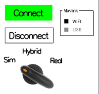
The idea here is to use the same application to mission a real or a simulated quad copter and get a movie or a stream of shots. In figure 8, the “Sim” mode ignores all the MAVLink functionality; the “Real” mode silences all simulation components while the “Hybrid” mode mixes both. In the latest mode, a wizard layer automatically superimposes simulated and real data using curves.
MAVLink
Controlling and flight-planning the quad copter needs to interface with MAVLink protocol (through a GPS recorder module that is sold apart). MAVLink is a communication standard for micro-air vehicles (MAV) that is supported by several vendors, compared to STANAG 4586 which is a North Atlantic Treaty Organization (NATO) UAV communication standard for interoperability (NATO, 2012). Both are sharing similar concepts and procedures.
MAVLink is a free and simple protocol to code, based on a stream of only 17 bytes data packets exchanges between the GCP and the MAV (Balasubramanian, n.d.). The list of messages is described in an XML format and covers many parameters and functions. For the sake of simplicity, the set of supported messages have been reduced to some flight-planning and direct commands only.
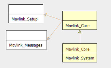
Fig. 9: Components
Architecture has been modified to include some MAVLink components as shown in figure 10.
“Mavlink Core” is responsible of raw connection with the quad core (i.e., flight recorder module) using either a WiFi socket or the USB serial.
“Mavlink Sys” translates supported commands into events and data for the “Logic” to handle. Conversely, the GCP redirects input data and trajectory status to “Mavlink Sys” and “Mavlink Core” down to the quad copter navigation system.
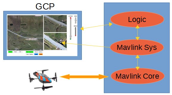
Fig. 10: Including MAVlink System
Tuning
The linear models must be tuned with the real UAV before allowing it
autonomous flight. In the office, some basic MAVlink connection using standard messages (e.g., take-off, land, goto, hold) are used to validate the communication scheme. Outside, on an empty parking lot, some maneuvers are sequenced in order to produce multiple curves that will later be used in replacement of the simple linear models.
Figure 11 shows the comparison of the altitude over time received from the quad copter (blue curve) for a hovering of 40 meters. The green line is the linear model. Different curves are produced with different combinations of speeds and altitudes. All curves, gathered as family of curves on 3 axis, give a surface of values with a fair accuracy. Linear extrapolation is therefore made for outbound values.
The purpose is less to replicate the exact quad copter behavior than to remain accurate enough on the overall mission outputs and performances.
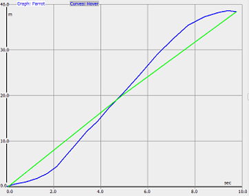
Fig. 11: Vertical Hovering Data
GOING ON FIELD
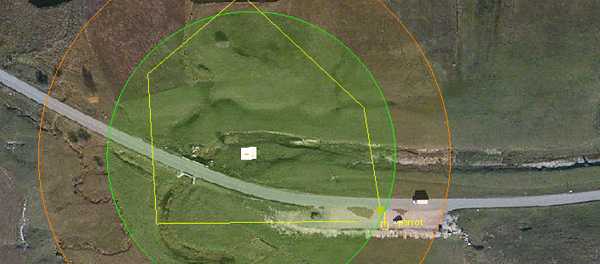
Now the quad copter correctly responds to the GCP, it is interesting to test the navigation beyond the WiFi range of 50 meters (green area), by using an antenna connected to the USB port of the laptop (figure 12, red zone).
The A.R. Drone used in this project got only one high-definition front camera. It is difficult to bent it without breaking the wires. A small mirror is glued in front of the lens to film the ground below. Considering the bank angle of the quad copter at maximum speed, only 30° angle were sufficient for the mirror tilt. Also, because the mirror inverts the image, a vertical flip post-process is applied on the movie and photo shots.
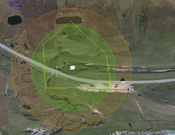
Fig. 12: Laptop Control Flight
The copter correctly flies the trajectory on a MAV_GOTO_DO _CONTINUE message and the front camera is able to send the video using MAVLink messages down to the GCP for comparison with the simulated camera. Continuous circling at different speeds and altitudes are performed until battery exhaustion, producing valuable curves of data for all simulated components (including the battery consumption).
Autonomous flight
Figure 13 shows a 1200 meters autonomous flight at 60 meters altitude. The trajectory has been downloaded to the GPS Recorder as a basic flight-plan. In such mode, the front camera is recording the video directly on the USB device and is no more broadcasting it. Because the laptop is out of WiFi range, the video is in all ways not receivable. All the flight data is stored on the device.
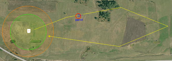
Fig. 13: Autonomous flight at replay for cross-checking data
The quad copter flies the plan at maximum speed during 6 minutes then returns to the WiFi area zone. The GCP is able to regain control and land the copter safely. The recorded video is then downloaded to the laptop with flight data (speed, position and altitude) for replay and comparison with the simulated position (figure 13, red circle)
During the real flight of the drone, even if no video nor position were received by the GCP, we were able to monitor the quad copter visually on the map and crosscheck its location with a binocular. Both the real copter and the simulated one reached the trajectory outer part at same time (a person raised a flag when the copter verticals him).
CONCLUSION
In this paper, a scenario generation toolkit was used to prove an autonomous flight before realizing it on the field. The simulation debrief and live-tuning can save time and equipment to prepare more complex missions, under difficult meteorological conditions (e.g., wind, fog) that do impact the visibility and autonomy of the UAV.
Nevertheless, we have faced three limitations that encourage even more the use of simulation:
1- The autonomy of such toys-like quad copter reduces drastically the usefulness of an unmanned mission. 10 minutes flight at 3 m/s gives only 1800 m flying distance, which is not enough for serious operations.
2- Regulation forbids the use of flying objects by amateurs above 150 m or out of sight, which is exactly the purpose of a UAV mission (Deneuvis, 2012). We were outlaw during our last experiment.
3- Mission update nor video signal are possible once out of the WiFi coverage (with this particular drone). Using an embedded smart-phone (connected by 4G to the GCP and using WiFi to communicate with the drone) could fix this issue and allow dynamic and/or live scenarios. However, with the battery limitation, such complexity in the design would be an overkill.
From the results of this project and if the live video is not mandatory, mission preparation on a synthetic environment is an effective approach for complex or furtive missions. To some extend, returning home can even be discarded: The UAV is launched from a car and recovered by another one somewhere else, thereby doubling the mission range and increasing its stealth.
REFERENCES
Anderson, C., (2012). How I accidentally kickstarted the domestic drone boom. Wired. Retrieve
Balasubramanian, S., (n.d.). MavLink Tutorial for Absolute Dummies. Retrieve
D’Andrea, R., (2013). The astounding athletic power of quadcopters. Presented at TEDGlobal 2013, Edinburgh, SCT. Retrieve
Deneuvis, O., (2012). Réglementation pour la prise de vues aériennes avec drone. Retrieve
Institute for Near East and Gulf Military Analysis, (2011, October 17). Drones: A new chapter in modern warfare.
Retrieve
Munoz, C.A., (2014, April). Object tracking using autonomous quad copter. Presented at the ASEE 2014 Zone I Conference, University of Bridgeport, Bridgeport, CT. Retrieve
New bird shaped UAS, (2013, April 13). sUASNews. Retrieve
North Atlantic Treaty Organization, (2012). STANAG 4586 (Edition 3) – Standard interface of UAV control system (UCS) for NATO UAV interoperability . Brussels, BD: NATO Standardization Agency – Agence OTAN de normalisation. Retrieve
Parrot, S.A., (2012). AR Drone 2 specifications & Review. Retrieve
QgroundControl, (n.d.). MAVLink Micro Air Vehicle Communication Protocol. Retrieve
VirtualSim, Sarl., (2014). vsTASKER 5 – Real-time simulation toolkit. Retrieved from